- About MAA
- Membership
- MAA Publications
- Periodicals
- Blogs
- MAA Book Series
- MAA Press (an imprint of the AMS)
- MAA Notes
- MAA Reviews
- Mathematical Communication
- Information for Libraries
- Author Resources
- Advertise with MAA
- Meetings
- Competitions
- Programs
- Communities
- MAA Sections
- SIGMAA
- MAA Connect
- Students
- MAA Awards
- Awards Booklets
- Writing Awards
- Teaching Awards
- Service Awards
- Research Awards
- Lecture Awards
- Putnam Competition Individual and Team Winners
- D. E. Shaw Group AMC 8 Awards & Certificates
- Maryam Mirzakhani AMC 10 A Awards & Certificates
- Two Sigma AMC 10 B Awards & Certificates
- Jane Street AMC 12 A Awards & Certificates
- Akamai AMC 12 B Awards & Certificates
- High School Teachers
- News
You are here
The Theorem that Won the War: Part 1.1 – Rotors
Mechanically, an Enigma machine consisted of a set of encryption drums or rotors. The rotors have contact points on each side, joined by wires. It’s convenient to think of these contact points as representing letters, with the wiring joining two letters of the alphabet. When an operator pressed a letter, an electrical current flowed between the contacts, lighting up the encrypted version of the letter.
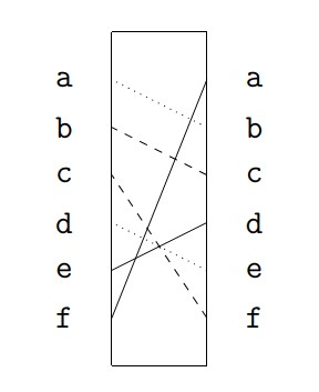
For our paper Engima, we’ll consider a six letter alphabet: \(a, b, c, d, e, f\). A “side” view of a rotor might look like the following (the different line styles have no significance, and they are only used to make it easier to distinguish between connections):

Figure 5. Side view of a rotor. All diagrams in
this article were created by the author.
In the diagram in Figure 5, the left-side \(a\) is connected to the right-side \(b\); the left-side \(b\) is connected to to the right-side \(c\); and so on.
Before we can describe this mathematically, we need to make a decision: Since electrical current can flow along a wire in either direction, we must choose a direction, either left-to-right or right-to-left. For example, if current is flowing from left to right, then the (left side) \(a\) is connected to the (right side) \(b\). Consequently, if the operator pressed \(a\), the current would light up \(b\), which would be the encrypted version. We might write this as \(a \rightarrow b\).
We can compile all of these left-to-right encryptions in tabular form as
\[\left(\begin{array}{cccccc} a & b&c &d &e &f \\ \downarrow &\downarrow &\downarrow &\downarrow &\downarrow &\downarrow \\b&c&f &e&d &a \end{array}\right)\]
Mathematically, we've taken the letters in the order \(a, b, c, d, e, f\), and rearranged them as \(b, c, f, e, d, a\). This is an example of what mathematicians call a permutation.
If we omit the down arrows and enclose everything in parentheses, we can represent our encryption in Cauchy two-line notation:
\[\left(\begin{array}{cccccc} a & b&c &d &e &f \\ b&c&f &e&d &a \end{array}\right)\]
Perhaps surprisingly to readers familiar with Stigler’s law of eponymy, Cauchy two-line notation is named after its inventor, Augustin-Louis Cauchy (1789–1857); you can read his original 1815 publication (en Français) here.
What if our current ran from right to left? In that case, we can represent our permutation as \[\left(\begin{array}{cccccc} a & b&c &d &e &f \\ f&a&b &e&d &c \end{array}\right)\]
To explore the basics of rotor design and permutations further, continue to the Activities for Part 1.1 (Rotors).
Return to the overview of Part 1 (Enigma on Paper).
Skip to the overview of Part 1.2 (The Enigma Encryption).
Jeff Suzuki (Brooklyn College), "The Theorem that Won the War: Part 1.1 – Rotors," Convergence (October 2023)


